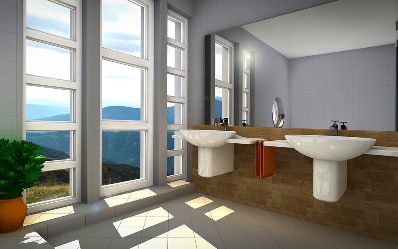

Architectural models on a computer are created using a number of programs. One of the best is CAD (Computer Aided Design), or rather, its subspecies ArchiCAD, a program made by Graphisoft specifically for architects. It creates 2D and 3D sketches, models based on sketches with the addition of photorealistic textures, and project visualization. The program models not only individual buildings and interiors, but also complexes of urban buildings.
Other programs for architects:
- Revit;
- AutoCAD Architecture;
- AutoCAD Civil 3D – more suitable for engineering communications;
- Chief Architect – better suited for home design;
- Rhino3D;
- CATIA;
- SketchUp – helps with architectural sketches and drawings;
- 3D Studio Max;
- Solidworks – more suitable for engineers.
After planning the model, the next step is to choose the scale that best suits a particular project. This decision is influenced by two factors: area and detail. If you need to show large areas, such as architectural models of cities, set the scale to 1:500 or 1:1000. This way, the model will not be too large and will be easily accessible for viewing.
For a single building, choose a scale of 1:200 or 1:100. At this scale, you get a fairly detailed detail, and windows, doors, and balconies will be clearly visible. To show only part of the house, a scale of 1:20 – 1:50 is suitable. The larger the scale, the more details you can distinguish.
How to make an architectural model: houses, neighborhoods, cities
Creating a model in any program follows the same principles. A building or complex of buildings is assembled from elements: windows, doors, walls, ceilings and floors, and so on. One model contains hundreds or even thousands of elements – the number depends on the object of modeling and the taste of architects. Different designers include different elements in their creations.
Stages of model creation:
- construction of sealed solid frames;
- removal of unnecessary holes;
- checking the topology and counting polygons;
- inverting the normals;
- finding overlapping surfaces;
- Removal of moving elements;
- smallest printable features (SPF);
- enhancement and support;
- architectural layout must be empty;
- removal of unnecessary geometry.
Create impermeable elements and remove dips
3D printers like to be given models that consist of geometrically correct objects – wireframes. Elements should not be permeable, for example, a hexagon has all six faces. If it has only five faces, then it is an open frame with a hole. Geometry with holes is often printed incorrectly.
When removing holes, use the rule: all adjacent triangles have two vertices in common. This way, a continuous surface without gaps is achieved. They are removed by special applications and manually.
Dips in the surface also occur due to file conversions from one format to another. Sometimes the number of missed or distorted polygons is so large that you have to align them manually.